
Speed alone doesn’t define a capable data center network; the physical pathways do. Structured cabling is an organized system of fiber and copper links, pathways, and connection points that carries network traffic between rooms, racks, switches, and servers. Cat 6A or better copper can support up to 10 Gbps across up to 100 meters. In data center network cabling engineering, cable selection, routing, topology, and certification shape whether those links meet performance targets and support future changes.
That’s why data center network cabling engineering is more than planning a collection of connections. The design must account for data flow, link testing, and how infrastructure can be maintained or expanded without undermining availability.
This article explains what structured cabling includes and how engineering decisions shape fiber performance, certification, reliability, scalability, and sustainability. It also covers standards and redundancy concepts that inform infrastructure planning, helping you understand how cabling decisions affect a data center throughout its operational life.
Key Takeaways
- Understand how structured cabling organizes connections between data center spaces, racks, and network equipment.
- Learn how fiber type, link-loss budgets, and certification affect whether connections meet performance requirements.
- See how cabling standards and availability ratings inform infrastructure planning and redundancy decisions.
- Compare the roles of fiber and copper, and how pathway design can support upgrades and operational changes.
- Recognize how topology, resilience, and energy-use measures shape reliable, scalable, and more sustainable infrastructure.
What is data center structured cabling?
Structured cabling organizes network connections through planned pathways, cable types, and termination points. Good design connects bandwidth requirements with installation, maintenance, and future changes.
Cable Pathways and Installation Management
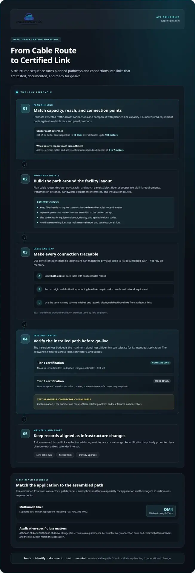
Pathways are planned cable routes through trays, racks, and patch panels. They protect and organize cables, while overcrowded routes make maintenance harder and can obstruct airflow. Keep fiber bends no tighter than roughly ten times the cable’s outer diameter. Separate power and network routes according to the project design, and size pathways for the facility’s equipment layout, density, and applicable local codes.
Cable Labeling and Documentation
Label each cable and endpoint with an identifiable record, then document how connections map to racks, panels, and network equipment. This lets technicians trace a link during maintenance or a change. A practical sequence is to route each cable, label both ends, record its origin and destination, then test and document the result before go-live.
Consistent identifiers help distinguish backbone links between systems or floors from horizontal links to servers and switches. BICSI guidelines provide installation practices used by field engineers. Apply the same naming scheme to labels and records so technicians can match physical cables to documented paths without relying on memory.
Cable Reach and Capacity
Reach is the distance a cable can carry a signal within its performance limits; capacity describes the bandwidth available across the links. Cat 6A or better copper cabling can support up to 10 Gbps over distances up to 100 meters. To estimate capacity, total the expected traffic across connections, then compare it with the capacity of the planned links. Port density is assessed by counting required equipment ports against available rack and panel positions.
For rack-to-rack links where passive copper reach is insufficient, active electrical cables and active optical cables handle distances of 3 to 7 meters. These choices affect pathway space, port placement, and how connections can be serviced.
Fiber and Copper Cabling
Fiber-optic cables transmit data using light; copper cabling carries electrical signals. This distinction matters when matching transmission distance, bandwidth, equipment interfaces, and installation routes. Multimode fiber serves data center links, while copper can connect equipment when its reach and performance suit the design. Select cable types to meet link requirements, not by material alone.
For example, a design may use fiber for a backbone between areas and copper for a shorter equipment connection. That combination affects pathway planning, patch-panel layout, and the space needed at each rack.
Fiber insertion-loss budgets and certification
An insertion-loss budget sets the maximum signal loss a fiber link can tolerate while meeting its intended application. Engineers allocate that allowance across the link, including fiber, connectors, and splices. The application’s requirements and the assembled path determine how much loss the link can sustain. This calculation matters because a connected link may still fail to support its planned transmission.
Testing and Certification
Tier 1 certification measures the insertion loss of the complete fiber link in decibels using an optical loss test set. The result shows whether the installed path meets its applicable performance requirements. Some cable manufacturers may require Tier 2 certification, which uses an optical time domain reflectometer to examine the link in greater detail.
Test and certify cabling at installation, before go-live, against the applicable standard’s performance requirements. Contamination is the number one cause of fiber-related problems and test failures in data centers, so connector cleanliness is essential to test readiness. Recertification is typically prompted by a change, such as a new run, moved rack, or density upgrade, rather than a fixed calendar interval.
Multimode Reach and Server Connectivity
Multimode fiber supports data center applications including 10G, 40G, and 100G. OM4 multimode fiber supports 100G transmission over distances up to roughly 150 meters. A multimode backbone can connect network areas while supporting 10G and 25G server connections, provided the chosen transceivers and link budget match the application.
Applications such as 40GBASE-SR4 and 100GBASE-SR4 have stringent insertion-loss requirements. That makes the combined loss of the installed path important: connectors, patch panels, and splices all contribute to the measured result. A design that accounts for each connection point can better align link capacity with the intended devices.
Modular Connectivity and Fiber Utilization
Modular, pre-terminated fiber connectivity uses assembled cable and connector systems to create repeatable links between patch panels and devices. It can simplify installation planning by defining connection points before routing cables. The design still needs to account for link length, connector count, and the application’s loss allowance.
Base-8 design organizes fiber connectivity into consistent groups, helping planners allocate strands across equipment links and backbone paths. Its value depends on matching the grouping to transceiver interfaces and planned port use. Mapping each group to patch panels and destination devices helps expose unused capacity and avoid mismatched connections.
Campus and Outside-Plant Links
Outside-plant and campus fiber extend connectivity between buildings or data center areas. Design must account for the full route and every termination, not just equipment-room patch panels. Record the path, endpoints, and test results so the installed link can be assessed as one system.
Where fiber routes must integrate with broader network planning, ICT infrastructure design can address how connectivity serves the facility’s systems and operational requirements.
Data center cabling standards and availability ratings
Standards give data center teams a shared framework for cabling performance, layout, and infrastructure planning. ANSI/TIA-942, ISO/IEC 11801, and BICSI publications address different parts of that work; system design then maps equipment, pathways, and functional areas to the facility’s operating needs.
Start with the facility’s availability and transmission goals, then plan cabling routes, connection points, and redundancy accordingly. The chosen framework helps coordinate these decisions across enterprise environments and planned upgrades.
Cabling Standards and Design Frameworks
Data center cabling standards define reference frameworks for system layout, performance, and infrastructure planning. A shared framework helps designers, installers, and operators align on consistent terms and system boundaries.
ANSI/TIA-568 sets rules for structured cabling performance and layout, while ISO/IEC 11801 provides global classification for cabling systems. ISO/IEC 24764 is cited for data center cabling design and infrastructure planning. ANSI/BICSI-002, identified as the 2024 edition, covers data center design and implementation. BICSI guidelines also provide installation practices used by field engineers.
ANSI/TIA-942 Infrastructure Standard
ANSI/TIA-942 is a standard for data center cabling design and infrastructure planning. Its role matters when teams need to coordinate telecommunications infrastructure with facility design and availability objectives.
ANSI/TIA-942-C, the data center telecommunications infrastructure standard, was published in May 2024. It replaced ANSI/TIA-942-B, published in July 2017. ANSI/TIA-942-C defines four infrastructure ratings for data center redundancy. Rating 4 requires redundant cabling pathways that can independently support the full facility load without an outage during maintenance.
Redundancy can also be described as N+1, meaning one more component than needed for operation. A rating and a redundancy model describe related but distinct design considerations; neither should be treated as a substitute for mapping the actual pathways and supported loads.
Structured Cabling System Design
Structured cabling design translates facility needs into a coordinated layout of functional areas, pathways, and connections. A clear design links operational objectives with transmission paths and planned upgrades.
Begin by identifying equipment locations and the connections between them. Separate backbone cabling between systems and floors from horizontal cabling that connects devices such as servers and switches. ANSI/TIA-942 and ISO/IEC 24764 provide data center planning references, while ANSI/TIA-568 addresses cabling layout and performance.
Document routes, connection points, and redundancy. For availability planning, show how alternate pathways support the intended load during maintenance. Relate each route to the facility’s required rating and operating model. This gives enterprise teams a consistent basis for reviewing infrastructure changes, latency-sensitive transmission paths, and future upgrades.
Data center structured cabling infrastructure
A data center cabling system combines backbone and horizontal links, pathways, patch panels, racks, and optics. Each component must suit the facility’s network architecture and equipment layout.
Future-Ready Cabling Infrastructure
Future-ready infrastructure reserves usable pathways and connection capacity for later equipment changes. Cabling typically outlasts two or three generations of switches and servers, so a design that only fits the current rack layout can constrain future upgrades even while the installed cable remains functional.
Plan around expected link types, fiber counts, rack locations, and the room available for cable management. Single-mode fiber is increasingly preferred for deployments targeting 100G, 400G, and 800G. Choosing a backbone approach with those targets in mind can preserve options as optics and connected equipment change.
Capacity planning also covers physical infrastructure. Tray space, patch-panel positions, rack access, and route separation affect whether new links can be installed without obstructing existing connections. Document these constraints alongside the network plan to make future expansion easier to assess.
800G and 1.6T Infrastructure Planning
Planning for 800G and 1.6T means aligning cabling paths, fiber availability, and optical interfaces with the intended network evolution. This matters because a higher-capacity optic is useful only when the full link and its connected devices support the design.
Data center operators are shifting to 800G optics, with 1.6T deployments expected to follow. Treat that progression as a planning input, not a reason to assume every link needs the same configuration. Map which connections are backbone links, which serve servers, and where existing patch panels can accommodate future changes.
Review link routes, fiber allocation, rack-level terminations, and optic compatibility together. This can reveal constraints before an upgrade, such as limited pathway capacity or a mismatch between installed fiber and the planned interface. Keep design records tied to specific routes and endpoints.
Cabling Infrastructure Components
The main components are backbone and horizontal cables, racks, trays, patch panels, connectors, and optics. Coordinate them carefully: every link depends on a continuous path between network equipment and its endpoint.
Backbone cabling connects network areas or floors; horizontal cabling connects equipment within those areas. Patch panels provide managed termination points, while racks position switches and connected devices. Fiber and copper suit different link requirements, so the system design must match cable type to distance and equipment interface.
Physical layout also affects operating conditions. Cable density and routing can influence access to equipment and airflow management. Cooling accounts for 30% to 50% of total data center energy consumption, so avoiding obstructed equipment paths supports broader facility planning. The cabling layout should coordinate with rack placement and cooling design rather than treating pathways as isolated infrastructure.
Reliability, flexibility, scalability, and sustainability
Reliable cabling depends on resilient routes, clear records, and capacity aligned with network operations. In the United States, engineering and installation costs depend on project scope; factors include cable types, route length, pathway work, density, redundancy, and testing.
Common risks include damaged links, incorrect connections, and unclear records. Route protection, consistent documentation, and testing help mitigate them.
Capacity Planning and Scalable Design
Capacity planning matches cabling pathways and connection points to current traffic and planned network growth. This matters because adding switches can strain crowded routes or leave too little termination space.
During design, map expected connections between racks, switches, and devices, then reserve suitable pathway and patch-panel capacity. Plan for 10G, 40G, and 100G upgrades during design, rather than treating each change as an isolated installation. This approach lets teams assess whether new links fit the existing architecture before work begins.
Reliability also depends on topology. A star topology connects each device to a central point, so one failed link doesn’t affect other links. Redundancy choices should reflect operational requirements: 2N means double the components required for operation, while 2N+1 adds one component to that doubled provision.
Scalability and Operating Costs
Scalability means expanding connectivity without replacing the entire cabling system. That matters because infrastructure can serve two or three generations of switches and servers.
Well-planned pathways and reserved connection capacity can reduce disruption during later changes. They also make links easier to trace during troubleshooting, helping teams isolate a signal problem to a route, connection, or device. Operating costs depend on how infrastructure is maintained and changed, not just on the initial installation.
Cabling Risks and Mitigation Practices
Risk mitigation combines physical protection, planned redundancy, and maintenance records. Poorly routed or documented links can complicate diagnosis and affect service continuity.
Keep pathways organized, preserve access to connections, and record changes to routes and endpoints. Many data centers recheck critical cabling links annually as part of routine maintenance. Test links after installation or significant changes, and retain the results with connection records.
Sustainability also belongs in operational planning. The Green Grid’s Power Usage Effectiveness (PUE) metric assesses how efficiently a data center uses incoming power for equipment. Its Water Usage Effectiveness (WUE) metric relates data center water use to IT equipment energy consumption, while Carbon Usage Effectiveness (CUE) measures greenhouse gas emissions per unit of IT energy consumed. These measures frame facility performance alongside cabling decisions. For infrastructure planning that coordinates network pathways with facility systems, plan integrated ICT infrastructure.
AVC Principles: AV Systems Design
AVC Principles provides ICT Infrastructure Design for projects where data center cabling must fit within a wider technology environment. Engage the team when planning a new facility, coordinating infrastructure with other systems, or assessing how an upgrade affects network pathways and equipment connections.
AV Systems Design and Command and Control Center Design can also support projects where network infrastructure must integrate with operational spaces and systems. The right design focus depends on the facility’s requirements and the systems it needs to support.
Contact AVC Principles to discuss your requirements for coordinated infrastructure planning.
Shape the Next Infrastructure Decision
Turn network requirements into a coordinated project brief. Identify the systems the facility must support, the operational constraints shaping its layout, and the changes the infrastructure may need to accommodate. This gives data center network cabling engineering a clear basis for decisions about technology, space, and future operations.
AVC Principles’ ICT Infrastructure Design helps align network infrastructure with the wider facility environment. AV Systems Design and Staged Environment Engineering address other technology and spatial design needs where they intersect with the project. Apply data center network cabling engineering to a defined operational challenge, such as a new environment, an upgrade, or closer coordination between systems.
Bring those requirements into a focused discussion and define the design priorities for your project. Contact AVC Principles to discuss your needs and take the next step with a clear direction.
Frequently Asked Questions
Do I need to comply with ANSI/TIA-942-C?
ANSI/TIA-942-C isn’t automatically a universal requirement for every data center; whether it applies depends on project specifications, owner requirements, and applicable authorities. It was published in May 2024 and replaced ANSI/TIA-942-B, published in July 2017. For a project, identify the required edition and rating in the governing design documents, then align infrastructure planning and review criteria with those stated requirements.
What are data center networking solutions and what do they include?
Data center networking solutions are coordinated systems that connect computing equipment and move traffic between endpoints. They can include switches, optical transceivers, fiber and copper links, patch panels, pathways, and network architecture. For example, a design connecting server racks to a core switch must account for ports, link media, route capacity, and management access. The solution is the working system, not one cable or device in isolation.
What’s the difference between structured and unstructured cabling?
Structured cabling uses an organized, documented layout with defined pathways, connection points, and labeled links. Unstructured cabling often develops through direct, ad hoc connections that make tracing and changing links harder. For example, a structured rack design maps patch-panel ports to switches and endpoints; an improvised arrangement may use individual cables wherever ports are available. This distinction affects how teams manage moves, additions, and troubleshooting.
What are the recommended cable types and distances for data center links?
Choose cable type and reach according to the link’s bandwidth, distance, and equipment interfaces. Cat 6A or better copper supports up to 10 Gbps over up to 100 meters. OM4 multimode fiber supports 100G over distances up to roughly 150 meters. Passive direct attach cable is generally reliable for connections up to about 2.5 meters; active electrical or optical cables handle rack-to-rack distances of 3 to 7 meters where passive copper reach is insufficient.
How do data center cabling designs support redundancy, scalability, and high availability?
Designs support these goals by providing alternate routes, reserving capacity, and separating connections so one link failure doesn’t interrupt unrelated links. A star topology connects devices to a central point, while redundancy can use N+1, 2N, or 2N+1 configurations according to the operating objective. For instance, mapped alternate pathways can support maintenance while preserving connectivity. Documented routes and planned capacity also make upgrades and fault isolation more manageable.
How do data center cabling requirements vary by facility size, location, and local codes?
Cabling requirements depend on the facility’s equipment layout and density, so size pathways accordingly. Separate power and network routes according to the project design and applicable local codes.